01
What is “No TIM Design”?
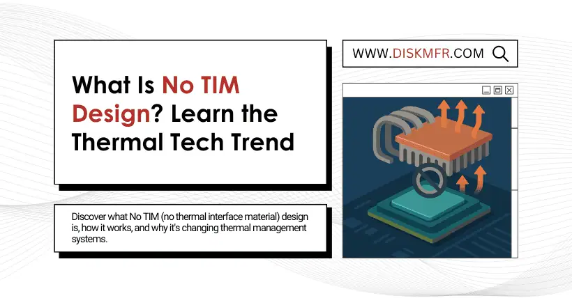
In traditional chip cooling structures, Thermal Interface Materials (TIM) are used to fill microscopic gaps between the chip and the heatsink to ensure smooth heat transfer from the chip to the cooler. Common TIMs include thermal paste, thermal pads, solder, or liquid metal.
“No-TIM design” aims to minimize or entirely eliminate the use of thermal interface materials, allowing the chip die to make direct contact with the cooler or heatsink, thereby removing the most significant layer of thermal resistance.
02
Why eliminate TIM?
Every contact layer introduces thermal resistance, which is one of the biggest obstacles to efficient heat dissipation.
For example:
Traditional chips are like heat sources covered in blankets—the heat must pass through several “blankets” to escape. No-TIM design allows the chip to touch the heatsink directly, as if removing the thickest blanket.
Advantages include:
- Lower overall thermal resistance: Removing the TIM shortens and streamlines the heat transfer path, significantly improving thermal conductivity.
- Improved cooling capacity: Especially for high-power chips (e.g., GPUs, AI accelerators, ASICs), this effectively reduces operating temperatures.
- Greater performance stability: Less thermal resistance helps suppress hotspots, resulting in more stable system frequency and performance.
- Simplified packaging structure: Especially suitable for delidded packages or “bare-die” cooling solutions.
03
How No-TIM Design Is Achieved
- Bare die directly contacts the cooler
The chip is packaged without a lid (IHS), allowing the cooler (such as a copper cold plate or liquid cooling module) to directly press against the silicon die. This requires:
- Precise contact pressure control
- Extremely flat contact surfaces
- Special surface treatment on the chip to enhance mechanical strength and thermal contact
- Using liquid metal instead of traditional TIM
If removing TIM entirely is too risky (e.g., the chip can’t withstand pressure), an ultra-thin layer of liquid metal (like gallium-indium alloy) can be used:
- Dozens of times higher thermal conductivity than thermal paste
- Can reduce interface thermal resistance significantly (typically down to 0.01°C/W)
- But care must be taken with its reactivity with aluminum and the risk of short circuits
- Thin system-level TIM (e.g., TIM 1.5)
In delidded packages, some manufacturers choose a compromise between no TIM and traditional TIM, using extremely thin high-conductivity materials to balance thermal performance and structural safety.
04
Technical Challenges and Limitations
| Challenge | Description |
|---|---|
| Mechanical stress management | Without TIM as a buffer, bare dies are more prone to cracking from thermal expansion differences |
| Extremely high flatness required | Contact surfaces must be extremely flat, or microscopic gaps will form thermal resistance |
| Liquid metal compatibility issues | Can corrode aluminum, contaminate PCBs—requires electrical insulation and material compatibility design |
| Complex heatsink mounting process | Requires precise contact pressure control to avoid damaging the chip |
| Increased cost | Higher-precision assembly, testing, and material substitutions raise costs |
05
Which chips use No-TIM design?
- High-performance GPUs (e.g., some engineering boards of NVIDIA A100, H100)
- AI accelerator chips (e.g., custom ASICs)
- Some server-grade CPUs (especially during high-power sample stages)
- Overclocking enthusiasts who delid consumer CPUs also fall into this category
06
Summary in One Sentence
“No-TIM design” essentially removes the “glue” from the heat transfer path, allowing direct thermal contact between the chip and the cooler to achieve extreme cooling efficiency—especially critical for high-power, high-performance chips, though it demands precise mechanical design, material compatibility, and process control for reliability and longevity.

Disclaimer:
- This channel does not make any representations or warranties regarding the availability, accuracy, timeliness, effectiveness, or completeness of any information posted. It hereby disclaims any liability or consequences arising from the use of the information.
- This channel is non-commercial and non-profit. The re-posted content does not signify endorsement of its views or responsibility for its authenticity. It does not intend to constitute any other guidance. This channel is not liable for any inaccuracies or errors in the re-posted or published information, directly or indirectly.
- Some data, materials, text, images, etc., used in this channel are sourced from the internet, and all reposts are duly credited to their sources. If you discover any work that infringes on your intellectual property rights or personal legal interests, please contact us, and we will promptly modify or remove it.


