
The emergence of any new technology is to address existing problems. NVMe was also developed to solve a current problem: the contradiction between the rapidly increasing performance of storage media and the poor performance of transmission channels. The performance of SSD-based storage devices is skyrocketing, but there has been no substantial improvement in the performance of SAS and SATA interfaces.
Currently, SAS and SATA based on the SCSI protocol can only have a single queue with relatively low depth, with queue depths of 254 and 32, respectively. NVMe, designed from the outset with this issue in mind, can support up to 64K queues (65,535 command queues and one administration queue), and each queue can have a depth of up to 64K. Compared to the SCSI protocol, it’s like the difference between a narrow country lane and a dual eight-lane highway.

01
Basic Principles of NVMe
To facilitate the understanding of the relationship between the host and NVMe devices, we simplify the internal structure of NVMe devices here. As shown in Figure 2 from the NVMe white paper, the host is referred to as “Host,” and the NVMe device as “Controller.” Interaction between the host and the controller is achieved through queues in shared memory.
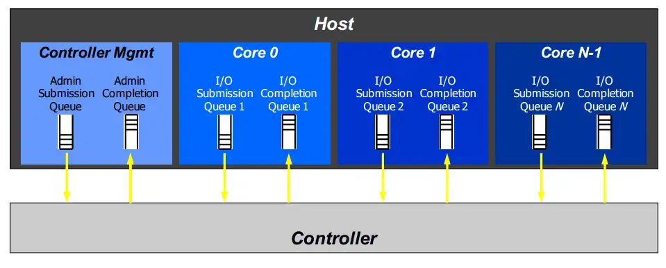
NVMe queues are of two types: one is used for management, known as the Admin Queue, of which there is only one, and the other is the Command Queue, which can have up to 65,535. The number and mode of command queues are set through the Admin Queue. Each queue is a pair of queues, consisting of a Submission Queue and a Completion Queue. The Submission Queue is used for the host to send NVMe commands to the NVMe device, while the Completion Queue is for the NVMe device to provide feedback to the host about the status of command execution. Additionally, there is another mode in NVMe where multiple Submission Queues share the same Completion Queue, which will not be discussed in this text.
02
NVMe Queue and Command Processing
From the previous discussion, we know that NVMe uses queues to pass control commands and other information. What exactly are these queues? The submission queue and the completion queue are just areas in memory. In terms of data structure principles, these queues are circular buffers, as shown in Figure 3.

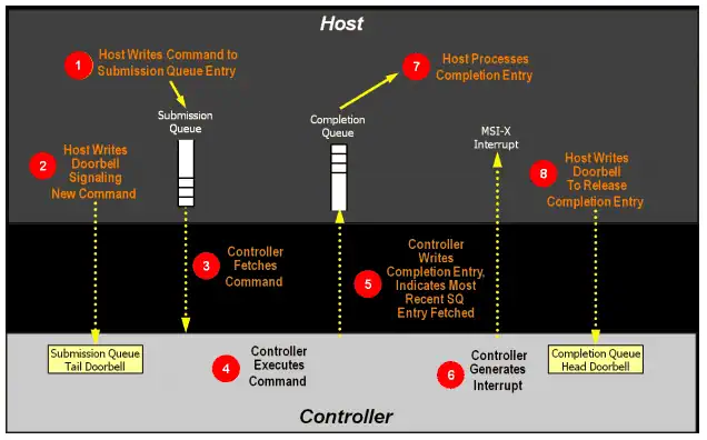
NVMe uses a doorbell mechanism to notify the controller whether the command queue has new data requests/commands. That is, each queue has a doorbell pointer. For the submission queue, this pointer represents the tail pointer of the queue. After the host writes data to the submission queue, it updates the tail pointer mapped to the device register space. At this point, the controller is aware of the new request/command and can begin processing it.
When the controller completes an NVMe request, it notifies the host through the completion queue. Unlike the submission queue, the completion queue uses an interrupt mechanism (which can be INTx, MSI, or MSIx) to inform the host. Figure 4 shows the complete processing flow of a command.
03
NVMe Command Format
Having discussed the command sending and processing flow, let’s now look at what an NVMe command looks like. Figure 5 shows the specific format of an NMVe command. If you are familiar with the TCP/IP or SCSI protocols, then understanding this diagram will be quite straightforward. In Figure 4, each row consists of 8 bytes, with the command size totaling 64 bytes.
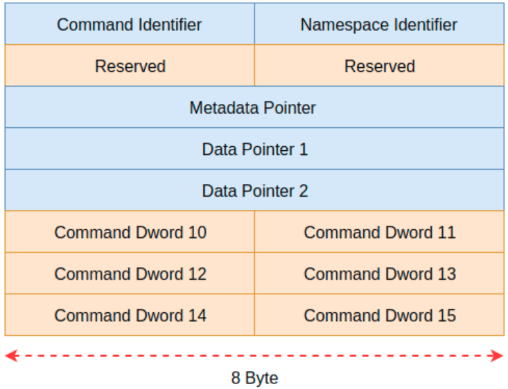
This command format includes several complex fields. Due to space limitations and to avoid overwhelming readers, not all details will be discussed here. Instead, we’ll briefly introduce a few key fields of this command format. The Command Identifier identifies a specific command. The Namespace Identifier indicates which namespace the command is sent to. Data Pointer 1 and Data Pointer 2 are used to specify the precise locations of the data.
Two points to note:
- An NVMe controller can have multiple namespaces, identified by the Namespace ID.
- Commands and data are separate, unlike in TCP where data follows the command.
Here, we focus on the Command Identifier, which occupies 4 bytes of space. Although it’s only 4 bytes, it is divided into 3 major parts and 6 minor parts, as shown in Figure 6.
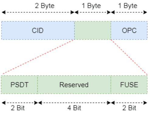
We will describe the meaning of each field from the least significant bit to the most significant bit:
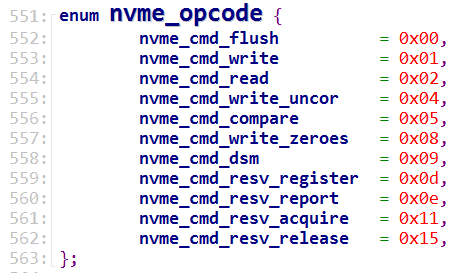
- OPC: Stands for Opcode, which is the operation code of the command being executed. Specifically, it defines what the controller is supposed to do, such as read data, write data, flush, etc.
- FUSE: Stands for Fused Operation, which indicates whether the command is a regular command or a compound command. Table 8 from the white paper explains this field.
| Value | Definition |
|---|---|
| 00b | Fused operation, the first command |
| 01b | Fused operation, first command |
| 10b | Fused operation, the second command |
| 11b | Reserved |
- PSDT: Stands for PRP or SGL for Data Transfer, which describes the organization of memory used to store data.
04
Performance of NVMe
Finally, let’s look at the performance comparison between NVMe, SAS, and SATA storage devices. To avoid any suspicion of advertising, this article will not specify the manufacturers and types of the devices.
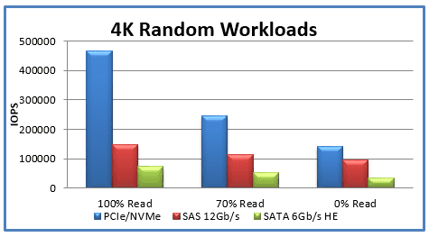
From the above figure, it is clear to see the performance difference between SAS and SATA devices compared to NVMe devices, especially in terms of read operations, where NVMe has a definitive performance advantage.

Disclaimer: This article is created by the original author. The content of the article represents their personal opinions. Our reposting is for sharing and discussion purposes only and does not imply our endorsement or agreement. If you have any objections, please contact us through the provided channels.


