
There are several commonly used tools for testing PCIe Gen5 M.2 SSDs, which can be categorized as follows:
- PCIe Gen5 Protocol Analyzers: Representative products include the SeriaTek PCIe Gen5 analyzer. These tools ensure stable capture and decoding of data when M.2 SSDs transition in and out of low-power L1.2 mode.
- PCIe Gen5 SSD Link Fault Injection Tools: Represented by Quarch’s Gen5 M.2 card control module, these products simulate various physical and link layer issues between M.2 SSDs and M.2 slots. They assess whether M.2 SSDs can operate reliably and consistently when connected to motherboards of varying quality in the market.
- PCIe Gen5 SSD Performance and Functionality Testing Devices: SanBlaze’s RM5/DT5 is a notable example in this category. It has been chosen by leading Gen5 M.2 SSD manufacturers worldwide for over a year. Particularly, it addresses the challenges of low-power L1.2 testing through unique hardware design. This article will focus on discussing the implementation of this feature.
- PCIe Gen5 SSD Voltage Deviation Testing: Quarch’s Gen5 M.2 PPM (programmable power module) is a representative product in this category. It tests the ability of Gen5 M.2 SSDs to function correctly when connected to different motherboards or when the motherboard voltage is unstable.
- PCIe Gen5 SSD Power Consumption and Sideband Signal Trace-back Tools: Quarch’s Gen5 M.2 PAM (programmable analysis module) is a notable product in this category. It facilitates convenient analysis of various issues with Gen5 M.2 SSDs when connected to different motherboards, especially in low-power L1.2 scenarios. The module allows engineers to capture voltage, current, power, and sideband signals like CLKREQ# and PERST# with high resolution over an extended period, enabling efficient troubleshooting and analysis.
- PCIe Gen5 SSD Test Environment Setup: Common components for setting up the testing environment include SerialCables’ Gen5 8-slot test chassis, along with various Gen5 M.2 adapter cards and extension cables (e.g., Gen5 M.2/AIC, M.2/U.2). The focus here is to ensure the quality of Gen5 signals.
- PCIe Gen5 SSD High-Low Temperature Testing Chambers: These products are divided into two categories: research and development (R&D) and production. For R&D purposes, the SerialCable RM5 can provide a temperature testing range of 0 to 75 degrees Celsius. In the case of production, customization is common to meet specific user requirements. Typically, a general-purpose temperature chamber architecture is employed, emphasizing the stability of Gen5 signals and the cost-effectiveness of the equipment.
Introduction to Low-Power L1.2 Testing
The SANBlaze SBExpress and Certified by SANBlaze testing methods greatly simplify the validation of PCIe NVMe devices by providing a straightforward approach to creating complex test suites, verifying compliance with specifications, ensuring data integrity, and conducting power, reset, and MI compliance tests.
With version 10.5 of the SANBlaze-certified test suite, SANBlaze introduces a set of tests specifically designed to validate the operation of NVMe devices under the ultra-low-power L1.1 and L1.2 substates.
L1.x substate testing presents unique yet crucial challenges for manufacturers of NVMe SSDs intended for battery-powered devices such as tablets and laptops. These devices can greatly benefit from the new power substates that trade a small amount of PCIe latency for the lowest possible power consumption.
The fundamental difference with L1.x substates lies in using out-of-band signals to “wake up” the device. By utilizing out-of-band signals, devices can achieve nearly zero power consumption by completely shutting down their transceivers and monitoring only the level of the CLKREQ# out-of-band signal.
Primary PCIe Power States
A comprehensive overview of PCIe power states, particularly L1.1 and L1.2 substrates, can be found in the PCI-SIG document available at https://pcisig.com/making-most-pcie-low-power-features. This document was authored by Scott Knowlton, Co-Chair of the PCI-SIG Marketing Workgroup. The following is a summary of the main PCIe power states:
- L0 – Active operational state of the link.
- L1 – Link state with no data transfer, allowing critical portions of the PCIe transceiver logic to be powered down.
- L2 – Similar to the L3 link state, but power has not been completely removed (not yet).
- L3 – Device in a powered-off state.
- L0s – A link state where data can be transmitted in one direction while potentially not transmitting data in the other direction. This allows both devices on the link to independently idle their transmitters.
Definition of L1.1 and L1.2 Substates
With the increasing speed and channel density of PCIe, keeping the PCIe channels active consumes significant power. According to the definition of the L1.2 power substate, entering low-power mode involves shutting down the PCIe transceiver PHY link and then reopening it when necessary.
To address this challenge, PCIe NVMe introduces an out-of-band signal called “CLKREQ#.” Its simplest definition is a “wake-up” signal from the host to the endpoint device, used to reopen the PHY and resume PCIe link communication. Shutting down the PHY can save a considerable amount of power and allows PCIe endpoint nodes to consume minimal power in idle mode. This is a significant improvement for battery-powered devices such as laptops.
The benefits of L1.x substates, as described in Scott Knowlton’s paper, are summarized below. For completeness, the text from the aforementioned specification is quoted here.
The fundamental idea behind the L1 substate is to wake up devices using something other than the high-speed logic within the PCIe transceiver. The goal is to achieve near-zero power consumption while in an active state.
This is accomplished by adding additional functionality to the existing PCIe pin (CLKREQ#) to provide a very simple signaling protocol. This allows the PCIe transceivers to shut down their high-speed circuitry and rely on this signal to wake them up again. In fact, this defines two new power substates: L1.1 and L1.2, each providing their own power-to-exit latency trade-off choices.
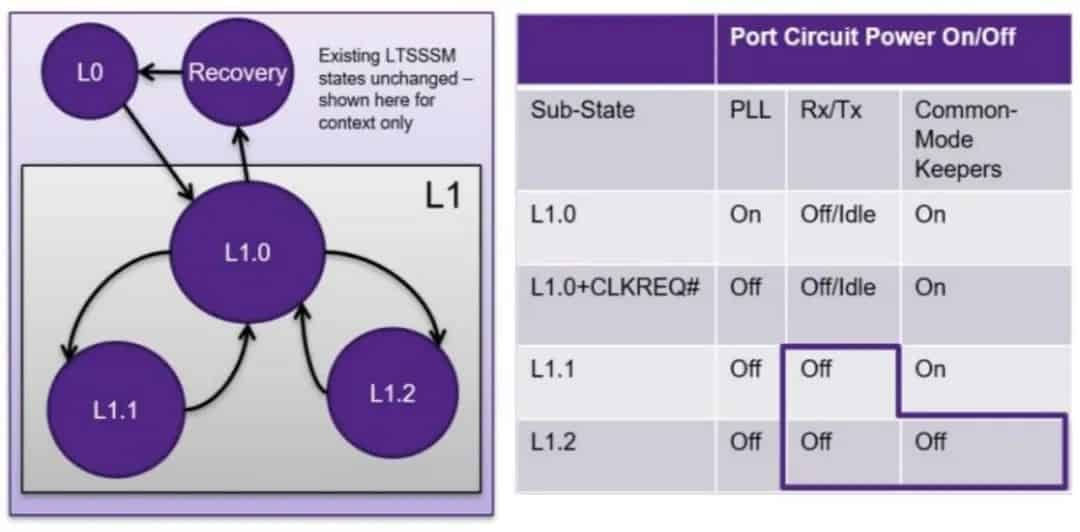
Both L1.1 and L1.2 allow the PCIe transceivers to shut down their PLLs as well as their receivers and transmitters, with L1.2 even allowing the shutdown of common mode keeper circuits.
The results are significant. Efficient circuit design and modern silicon processes mean that a typical PCI Express 4.0 x4 PHY (consisting of four transceivers plus associated digital logic for the four lanes) consumes power in the range of 400-500mW when operating at the full 16GT/s data rate in L0.
With L1.1, the power consumption of the same PHY is reduced by approximately 20 times, consuming only 20-30mW. Accepting slightly longer exit latency in L1.2 further reduces the power consumption by an additional factor of 10, reaching as low as 2-3mW.
The graph below illustrates the scale of power savings for multi-lane links compared to the existing low-power solution with an L1 substate. It is expected that the energy-saving scale of multi-lane links grows linearly, and implementing the L1 substate functionality reduces power consumption as the L1 exit latency increases. Implementing the L1 substate is a key factor in reducing power consumption for mobile designs utilizing PCIe.
Controlling CLKREQ#
As mentioned in the previous section, the CLKREQ# pin available on NVMe U.2, U.3, EDSFF, and M.2 connectors has been modified to provide a “wake” signal to M.2 SSD solid-state drives in power states L1.1 and L1.2, as shown in Figure 1.
In order to verify the proper operation of the L1, L1.1, and L1.2 low-power substates, users must be able to monitor and control the CLKREQ# signal. This can be achieved using the SANBlaze PCIe Gen5 NVMe Test System (software version V10.5).
CLKREQ# Signal
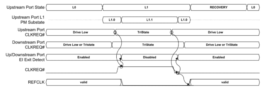
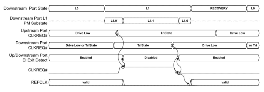
The CLKREQ# signal is asserted low when the device under test is in the L0 (full power) state and can be asserted by upstream or downstream devices on the PCIe link to transition the device from L1.1 or L1.2 back to L0.Active.
CLKREQ# L1.1 L1.2 Testing Modes
SANBlaze supports L1.1 and L1.2 testing on the SBExpress-RM5 (Rack Mounted PCIe Gen5 Test System) and SBExpress-DT5 (Desk Top PCIe Gen5 Test System) NVMe SSD test systems. Built-in scripts are currently available for use with SANBlaze hardware, and their operation is described below.
Depending on the physical placement of the device under test in the SBExpress-RM5 system, the test will run in one of two modes. The script will automatically determine the system configuration and run one of the two testing modes based on the system configuration and version.
Each operating mode has its own advantages, and it is recommended to test the Gen4/5 M.2 SSD under test in both modes, as described below.
The Scripts for Testing the L1.1 and L1.2 Low-Power Substates
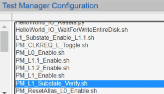
The following scripts are available in the SANBlaze V10.5 software package, which can be obtained from SANBlaze.
- PM_L1_Substate_Verify.sh
- PM_L0_Enable.sh
- PM_L1.1 Enable.sh
- PM_L1.2 Enable.sh
- PM_L1_Enable.sh
Here are the variations of the script “PM_L1_Substate_Verify.sh” that test the device under test for transitions from L0.Active to L1.Idle, L1.1, and L1.2. The script verifies the expected power state transitions of the device by checking the PCIe bus link state and the current status of the CLKREQ# signal at each level.
Variations include:
- PM_L0_Enable.sh – Restores the device to L0.Active state
- PM_L1.1_Enable.sh – Leaves the device in L1.1 state
- PM_L1.2_Enable.sh – Leaves the device in L1.2 state
- PM_L1_Enable.sh – Leaves the device in L1 (L1.0) state
Defined Modes for CLKREQ#
Currently, two testing modes have been defined to run the scripts on the SANBlaze SBExpress-RM5 hardware system, and all slots of the SBExpress-RM5 system can run Mode 1.
- Mode 1 – SANBlaze “riser” controls CLKREQ#
- Mode 2 – CLKREQ# signal controlled by upstream PCIe device
Please note that Mode 2 testing requires customized firmware and may involve on-site firmware upgrades.
In Mode 1 CLKREQ# Testing
In the first operating mode, the SANBlaze script controls the entry and exit of the L1.x substate by manually controlling CLKREQ#. This operating mode validates the substate and operates in all 16 slots of the SBExpress-RM5 testing system in the following manner.
Selecting “Test Manager” for Testing
The low-power substate testing scripts need to be manually selected, and they will also be included in the Certified by SANBlaze testing report.
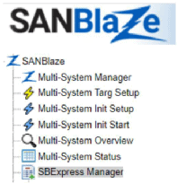
First, navigate to the SBExpress Manager page by selecting it from the left menu in the SanBlaze WebGUI:
Next, choose the “Show Test Manager” button located near the bottom of the page:

Afterward, select the “PM_L1_Substate_Verify.sh” script located on the right side:
At this point, you have the option to allocate the test to all devices and set either “Pass Time” or “Pass Count.” Pass Time will be used as the duration of stay between each substate transition, and the script will run for the specified number of pass counts before the final test is deemed “pass.”
For simplicity, let’s keep the pass count as 1 and allow the script to set the duration of stay.
Select the “Add Test” button. The test will be added to the selected devices.

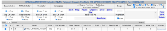
Your system is now preparing to run the low-power substate test on the selected devices, and the top section of the page should display the test as “Idle,” as shown below:
Select “Start” to initiate the test. The test will put the devices under evaluation into the L0.Active state, followed by entering each of the aforementioned L1.x substates.
Monitoring NVMe Sideband Signals
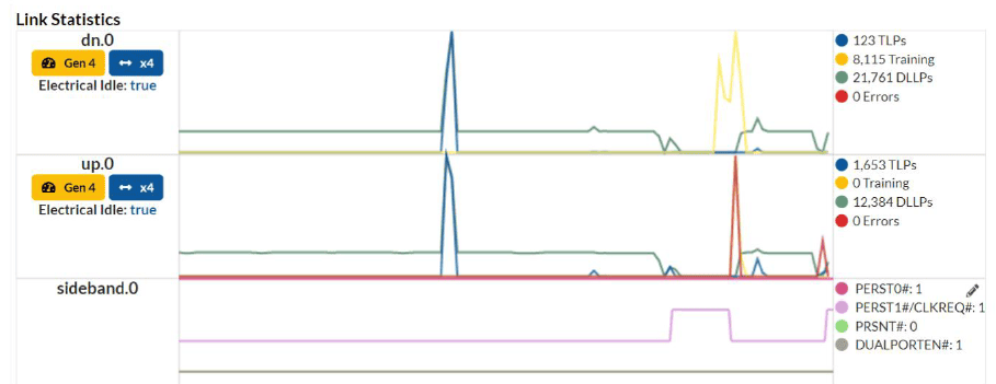
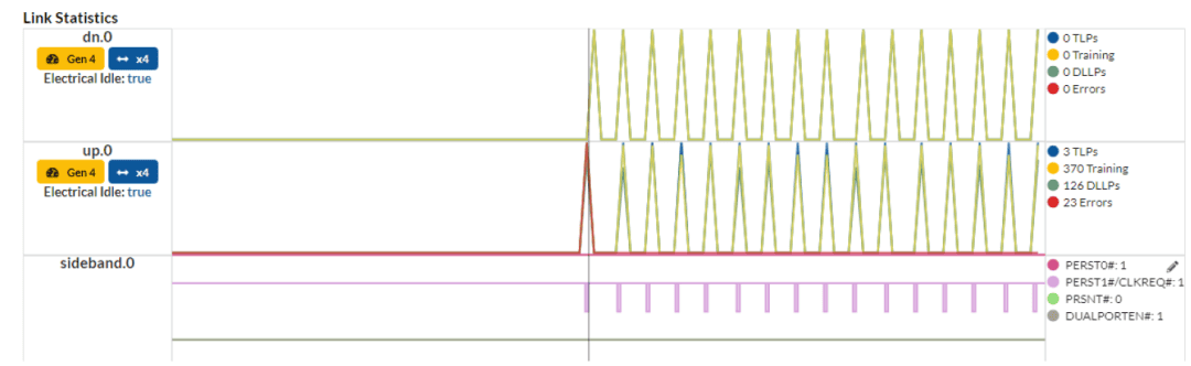
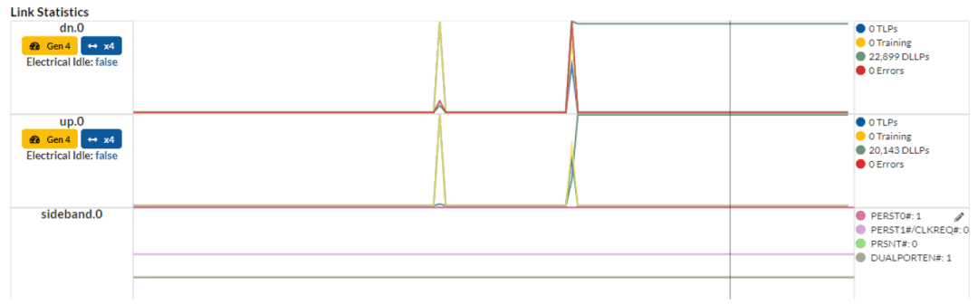
To demonstrate Mode 1 testing, we are utilizing the SerialTek Kodiak Gen5 PCIe/NVMe protocol analyzer to monitor link statistics and sideband signals such as PERST0#, CLKREQ#, PRSNT#, and DUALPORTEN#.
As seen in the trace, when the device under test de-asserts CLKREQ# and shuts down the PCIe “Phys,” you will observe the system transitioning to “Training.” This is the expected behavior for Mode 1 testing.
When the system asserts CLKREQ#, the device under test will retrain and become active on PCIe.
This script monitors the state of CLKREQ# and the PCIe link, testing the expected behavior for each transition.
At the end of the test, the device will receive a status of “Pass,” “Fail,” or “Warning.” For instance, if the device does not support the claimed low-power state, a warning may be issued.
Configuring NVMe Support Functionality
During the testing process, the execution of “GetFeatures” and “SetFeatures” commands is as follows:
First, the “GetFeatures” command is issued, and the supported number of power states (NPSS – Number of Power States Supported) value is read from the device.
Using SetFeatures, the generated NPSS value is sent to the device to enable the lowest possible power states. Once the device has been configured with this approach, it is expected to successfully enter and exit each low-power state.
Mode 1 Testing Results
In Mode 1 CLKREQ# testing, the M.2 SSD solid-state drive is expected to respond correctly to the GetFeatures command and accept the SetFeatures command to select the lowest power state. The M.2 SSD solid-state drive is expected to operate as follows; otherwise, it will fail the test:
- The M.2 SSD solid-state drive starts in full power mode, L0.Active.
- The M.2 SSD solid-state drive responds to the GetFeatures command.
- The M.2 SSD solid-state drive accepts the SetFeatures command to select the lowest power state.
- The script instructs the M.2 SSD solid-state drive to enter the L1.0 state using ASPMControl.
- The script enables the L1.1 state using L1PMControl.
- The script checks if the M.2 SSD solid-state drive has lowered CLKREQ#.
- The script checks if the PCIe link has transitioned to “Polling.”
- The script asserts CLKREQ# and verifies that the M.2 SSD solid-state drive returns to the L0.Active state.
- Steps 4-8 are repeated for the L1.2 state.
- The M.2 SSD solid-state drive returns to L0.Active, and the default values are restored to SetFeatures.
Conducting Mode 2 CLKREQ# Testing
In the second operating mode, the SANBlaze riser allows the upstream PCIe of the device under test to control CLKREQ#. The testing process follows the steps outlined in the Mode 1 testing.
The script will verify the availability of Mode 2 testing on the specified slots and automatically execute the Mode 2 testing.
Requirements for Mode 2 Testing
To perform Mode 2 testing (host-controlled CLKREQ#), the SBExpress-RM5 system must be configured as follows:
- The device Under Test must be in slot 0-7
- SANBlaze Riser supports passing CLKREQ# to host
- SANBlaze M.2 adapter supports passing CLKREQ# to host
- SBExpress-RMS system must have B0 revision silicon
If Mode 2 is not available, the script will evaluate the system and execute Mode 1 testing instead.
Execution of Mode 2 CLKREQ# Testing
In Mode 2 CLKREQ# testing, the M.2 SSD solid-state drive is expected to respond correctly to the GetFeatures command and accept the SetFeatures command to select the lowest power state. The M.2 SSD solid-state drive is expected to operate as follows; otherwise, it will fail the test:
- The M.2 SSD solid-state drive starts in full power mode, L0.Active.
- The M.2 SSD solid-state drive responds to the GetFeatures command.
- The M.2 SSD solid-state drive accepts the SetFeatures command to select the lowest power state.
- The script instructs the M.2 SSD solid-state drive to enter the L1.0 state using ASPMControl.
- The script enables the L1.1 state using L1PMControl.
- The script checks if both the M.2 SSD solid-state drive and the host have de-asserted CLKREQ#.
- The script checks if the PCIe link has transitioned to “L1.Idle.”
- The script sends IO to the M.2 SSD solid-state drive and verifies that the host asserts CLKREQ#.
- The script expects the IO to be successful.
- Steps 4-8 are repeated for the L1.2 state.
- The M.2 SSD solid-state drive returns to L0.Active, and the default values are restored to SetFeatures.
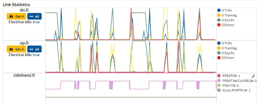
The trace captured by the SerialTek Kodiak PCIe Gen5 protocol analyzer will display the M.2 SSD solid-state drive in the L1.Idle state and verify if the host is asserting CLKREQ# in response to IO requests.
Explanation and Publication of Test Results
The successful completion of the substate testing will be displayed on the SBExpress page as follows:

Selecting the link name of the test, in this case, PM_L1_Substate_Verify.sh, will display the detailed log of the test execution. The log will provide a comprehensive record of the test steps, actions performed, and any relevant observations or measurements.
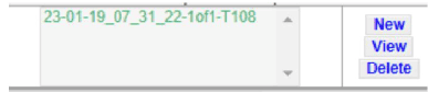
Select a name, and then “View” will display the test report, which can be exported or printed, including a summary of the results or the complete test log.
Unveiling the Behind-the-Scenes of CLKREQ# Testing
By utilizing the SerialTek PCIe Gen5 protocol analyzer, you can monitor the actual occurrences on the sideband and PCIe data path signals during the testing process. However, it is important to note that the substate testing does not require an analyzer.
Initiating Substate from the CLI
In addition to the provided scripts, you can also initialize and observe substate transitions from the SANBlaze Command Line Interface (CLI).
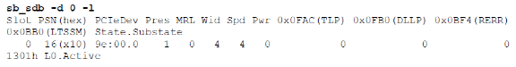
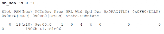
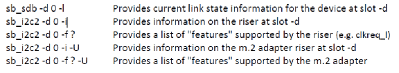
Checking Link Status with sb_sdb
sb_sdb is a tool that communicates with the PCIe switch via a serial bus. It can be used to query the link status of the switch. For instance, the current link status of the device located in -d 0 (the first slot on the left-hand side of the test device) is L0.Active:
In this scenario, we will employ sb_sdb to monitor the link status and conduct a step-by-step test on the M.2 SSD solid-state drive using power substates.
Enabling the Lowest Power State with SetFeatures
To begin, utilize the Getfeature and Setfeature functionalities to enable the lowest power state supported by the device. The target number is 100 + the slot number, hence the M.2 SSD solid-state drive in slot 0 corresponds to target 100.
Taking the M.2 SSD solid-state drive in slot 0 as an example = Target 100 = /iport0/target100
Next, determine the number of supported power states and enable the lowest power state. The following command will return the supported power state count:
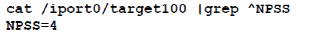
When it comes to power features, the highest power state appears first, so using the number from the command above will enable the lowest power state. Use the number 4 from the above command with the NPSS number to send the “SetFeatures” command for -d data as follows:

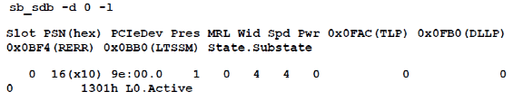
Now, you have used the SetFeatures command to inform the M.2 SSD solid-state drive about the desired lowest power state. However, it will still remain in the L0.Active state, as shown below:
Disabling the System Watchdog
The SBExpress system features a “watchdog” that polls every second unless disabled. This watchdog keeps the M.2 SSD solid-state drive in an active state. However, for testing purposes, it is necessary to disable it.

Disabling SMBus for the M.2 SSD Solid-State Drive
The SBExpress system reads data from the SMBus on the “adapter” of the M.2 SSD solid-state drive. SMBus activity keeps the M.2 SSD drive in an active state. Therefore, it is necessary to disable SMBus activity as well.

Enabling Low Power States with ASPM
Send the following ASPM command to enable L1.0 power state.

You will observe the M.2 SSD solid-state drive in the L1.Idle state (currently L1.0).
In this case, you will see that the SSD is not in the L1.x state because clkreq_l still shows as asserted.
Enable L1.1 or L1.2
Now, use this command to enable the L1 substate (8 = L1.1, 4 = L1.2).

At this point, the M.2 SSD solid-state drive will transition to the L1.2 substate and de-assert CLKREQ#. This can be observed through the sideband tracing on the SerialTek Kodiak PCIe Gen5 Analyzer, as shown below:
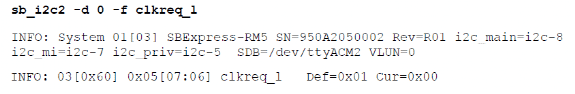
You can also use the following command to verify if CLKREQ# is now disabled:
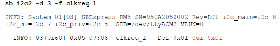
As shown, CLKREQ# is now inactive (0x01).
To initiate I/O for the M.2 SSD solid-state drive or assert CLKREQ#, the M.2 SSD drive can be reconnected, for example, by restarting the watchdog.
The behavior of the device under test will vary depending on whether the host or the SBExpress system controls CLKREQ#. The M.2 SSD solid-state drive will remain in L1 relative to the upstream port, or it may transition to a Polling state based on the slot number (0-7) or (8-15).
To manually restore the M.2 SSD solid-state drive to full power state, you can clear the settings mentioned above.
Additional Features of CLI Commands
During power state testing, the following CLI commands are particularly useful:
- sb_sdb – Performs out-of-band communication
- sb_i2c2 – Performs I/O to the system risers and adapters
Below are some examples that are useful for power state testing:
sb_i2c2 Command Example
Assert PERST on the device in Slot 0: sb_i2c2 -d 0 -f PORTO_PERST_L -w 0
De-assert PERST: sb_i2c2 -d 0 -f PORTO_PERST_L -w 1
Power off the device in Slot 0: sb_i2c2 -d 0 -f DISABLE_12V_L -w 0
Power on the device: sb_i2c2 -d 0 -f DISABLE_12V_L -w 1
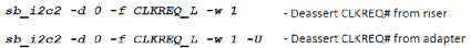
Reading and Writing CLKREQ_L
Please note that there may be multiple M.2 SSD drives driving CLKREQ_L, and because this signal is daisy-chained, any M.2 SSD solid-state drive that asserts it will keep it asserted, regardless of other devices. The SANBlaze script first uses the following command to de-assert CLKREQ on the selected riser and adapter:
When entering the L1 sub-state, the DUT (Device Under Test) will drive CLKREQ# low.
In Mode 2 – Host M.2 SSD Solid-State Drive (CLKREQ#), when the host sends an I/O request to the M.2 SSD solid-state drive, the host automatically asserts CLKREQ#.
In Mode 1 – the SANBlaze riser or adapter drives CLKREQ# to restore the M.2 SSD solid-state drive to the L0.Active state.
Conclusion
Within the vast realm of technological prowess, SANBlaze unveils a simple yet powerful method to test the elusive low-power states of L1.1 and L1.2. Behold, for they offer automated scripts, crafted with precision, to ascertain the power status of NVMe M.2 SSD solid-state drives that embrace the realms of L1 sub-states.
SANBlaze presents two extraordinary paths to validate the arrival of the desired state, where innovation intertwines with verification.
In Mode 1, a wondrous dance commences as the SANBlaze riser takes the helm, controlling the mystical transition of CLKREQ# through the enchanting scripts of SANBlaze or even the scripts bestowed by esteemed customers.
In Mode 2, a symphony of control unfolds, where the very fabric of the host-based domain intertwines with the device. With each touch of data access, the host’s authority effortlessly asserts or de-asserts CLKREQ#, bringing forth a harmonious equilibrium.
Witness the wonder as automation weaves its magic, seamlessly integrating the tests into existing suites, and showcasing the results within the grand tapestry of the DUT’s final report.
To unlock the secrets, one may embark on a journey using the mystical SerialTek PCIe Gen5 protocol analyzer, adorned with the Gen5 M.2 interposer. With this ethereal tool, the seeker can witness the true essence of reality, monitoring the mystical dance of CLKREQ# signals and the ever-shifting landscape of link status in real time. Alternatively, one can delve into the depths of the system’s command-line interface, extracting these elusive states with a mere command, revealing the hidden truths that lie within.


