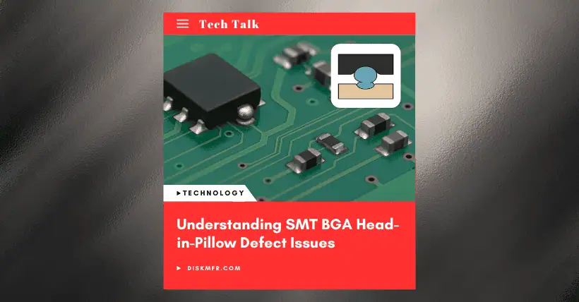
HIP is a typical failure mode in BGA (Ball Grid Array) or CSP (Chip Scale Package) reflow soldering, characterized by incomplete fusion between solder balls and solder paste, forming a “head-in-pillow” type of weak joint. It is highly concealed (can pass functional testing), but prone to mechanical stress failure later, threatening the long-term reliability of the product. Below is a systematic analysis and solution strategy:
01
Mechanism and Main Causes of HIP Formation
Thermal Deformation and Warpage
- Warping of BGA package or PCB during heating: In reflow soldering, due to CTE (Coefficient of Thermal Expansion) mismatch or rapid heating, local deformation occurs in the BGA substrate or PCB, causing physical separation between the solder ball and the solder paste. As the temperature drops, the two reconnect, but oxidation layers have already formed, hindering proper fusion.
- High-incidence areas of deformation: 99% of HIP occurs in the outer 1–3 rows of BGA solder joints (areas with maximum warpage).
Abnormalities on Solder Ball/Pad Surfaces
- Oxidation or contamination: Residue from test probes, excessive humidity during storage (MSL level out of control), or insufficient cleaning of water-soluble flux can lead to solder ball oxidation (SnO/SnO₂).
- Secondary oxidation: At high temperatures, flux activity is depleted, and oxidation on the molten solder surface worsens.
Process Parameter Imbalance
- Solder paste printing defects: Inadequate stencil apertures, misaligned printing, or vias in pad (Via-in-Pad) designs cause insufficient or uneven solder paste distribution.
- Improper reflow profile: Excessive preheat time (>100s) or temperature (>200°C) accelerates flux evaporation; excessive peak temperature (>240°C) worsens oxidation and deformation.
Material Compatibility Issues
- Low-activity solder paste: Flux with poor high-temperature oxidation resistance (e.g., Bi/In alloy pastes) results in inadequate wetting.
- Low Tg substrates: PCBs with low glass transition temperatures (Tg) soften and deform more easily under high temperatures.
02
HIP Detection and Diagnosis Methods
| Method | Principle & Advantages | Limitations |
|---|---|---|
| 3D X-ray CT | Tomographic scanning reconstructs 3D structure of solder joints to identify HIP areas | High equipment cost, slow inspection speed |
| Red Dye Test | Dye penetrates unfused gaps, visible after separation (destructive, high precision) | Requires sample destruction, complex operation (vacuum infiltration, curing) |
| Cross-section Analysis | Slicing solder joints for electron microscope observation | Destructive, sampling only |
| 2D X-ray | 45° rotation reveals “gourd-shaped” trailing phenomenon | Insensitive to vertical separation, easily missed |
Note: Functional testing (ICT/FVT) and Burn-In can screen some intermittent failures but with limited coverage.
03
Solutions and Prevention Strategies for HIP
Optimize Stencil Design and Solder Paste Volume
- Increase solder volume selectively for outer joints: Modify outer 1–3 BGA rows from round to square-in-circle apertures (e.g., Ø0.26mm → 0.25mm square, volume increases 13.6–24.97%), keep inner rows round.
- Increase area ratio (AR): AR > 0.66 ensures release efficiency and prevents insufficient solder.
Upgrade Solder Paste and Flux Activity
- Use high-oxidation-resistance solder paste: For example, replace low-silver formulas with SAC305 (Sn-Ag-Cu) to improve resistance to high-temp oxidation (case: HIP defect rate dropped from 3% to 0%).
- Add flux/N₂ reflow: Nitrogen atmosphere (O₂ < 500ppm) suppresses oxidation; localized flux spray directly activates solder ball surface.
Precisely Control Reflow Profile
- Shorten preheat time: Keep 150–200°C zone within 60–80s (previously over 100s) to preserve flux activity.
- Lower peak temperature: Set at 235–240°C to reduce deformation and oxidation.
Suppress Deformation and Strengthen Material Control
- Use reflow carriers: Support thin boards (≤1.0mm) or large-size PCBs to reduce secondary reflow deformation.
- High Tg boards and baking: Use PCBs with Tg > 170°C; bake BGA components (105°C / 4–8h) to remove moisture and prevent warpage.
- Supplier coordination: Require BGA vendors to control warpage (high-temp deformation < 80μm), and prohibit water-soluble flux ball-attach processes.
04
Practical Application Recommendations
Priority Order:
- First: Stencil optimization and solder paste upgrade (low cost, fast effect).
- Second: Reflow profile adjustments.
- Third: Carriers/N₂ reflow (higher cost).
Cross-process collaboration:
- Design: Avoid Via-in-Pad, optimize copper foil balance on pads (reduce local heat absorption).
- Placement: Calibrate Z-axis pressure (ensure solder ball contacts solder paste).
Inspection combination:
- Mass production: Use 3D X-ray sampling (once every 2 hours).
- Failure analysis: Confirm with red dye test or cross-sectioning.
“A narrow process window is the core contradiction behind frequent HIP issues” — expanding the process window through multi-dimensional improvements (e.g., defect rate reduced to zero simply by changing solder paste) can significantly enhance BGA soldering reliability.

Disclaimer:
- This channel does not make any representations or warranties regarding the availability, accuracy, timeliness, effectiveness, or completeness of any information posted. It hereby disclaims any liability or consequences arising from the use of the information.
- This channel is non-commercial and non-profit. The re-posted content does not signify endorsement of its views or responsibility for its authenticity. It does not intend to constitute any other guidance. This channel is not liable for any inaccuracies or errors in the re-posted or published information, directly or indirectly.
- Some data, materials, text, images, etc., used in this channel are sourced from the internet, and all reposts are duly credited to their sources. If you discover any work that infringes on your intellectual property rights or personal legal interests, please contact us, and we will promptly modify or remove it.


