The most widespread use of USB Type-C began with USB3.1, as the functionality of USB has since expanded.
USB3.1 Basic Specifications
| History | Max Transfer Rate | Name | Power Output | Power Supply | Date |
|---|---|---|---|---|---|
| USB 1.0 | 1.5 Mbps | Low Speed | 2.5W | 500 mA | 1996.1 |
| USB 1.1 | 12 Mbps | Full Speed | 2.5W | 500 mA | 1998.9 |
| USB 2.0 | 480 Mbps | High Speed | 2.5W | 500 mA | 2000.4 |
| USB 3.0 | 5 Gbps | Super Speed Gen1 | 4.5W | 900 mA | 2008.11 |
| USB 3.1 | 10 Gbps | Super Speed Gen2 | 100W | 900 mA | 2013.8 |
Comparison of output power and flag of Serial USB
- Full functions: data, audio, video transmission, and charging are supported at the same time, all concentrated in one transmission line, which can solve the problem of too many transmission lines.
- Support direct and reverse connection: Type-C footprint is a mirror design, it can support direct and reverse connection, the hardware has a special detection mechanism to determine whether it is a direct or reverse connection, this part will be mentioned later. (Midnight phone to charge without having to turn on the light to see the direction of the plug!)
- Two-way transmission: Data and power can be transmitted and charged in both directions.
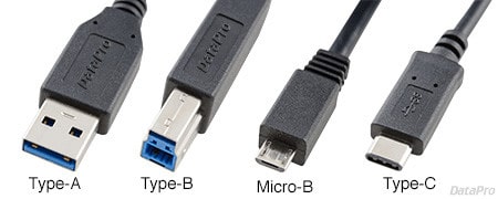
- Backward Compatibility: Supports USB Type-A and Micro-B interfaces via a dongle.
- Fast transmission rate: Support USB 3.1, which can support up to 10Gbps data transmission.
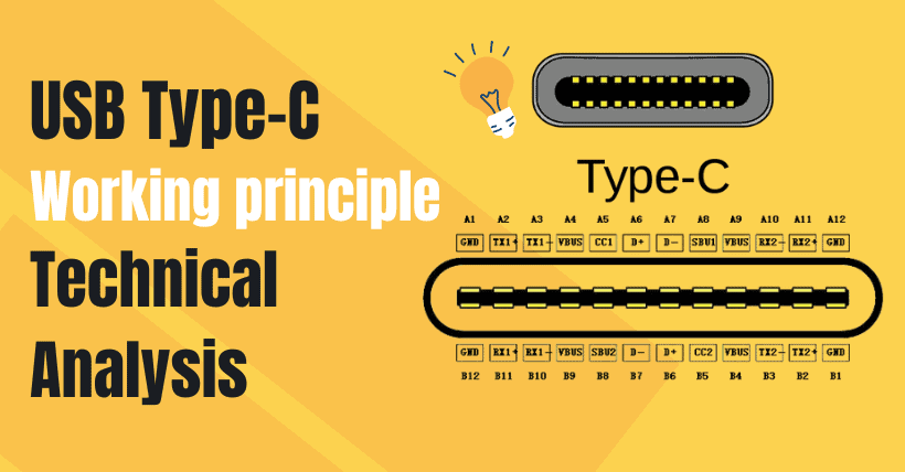
USB Type C pin function Overview
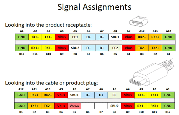
Pin Description:
- Tx/Rx: Two differential signal transmission pairs for data transmission.
- CC1/CC2 (configuration channel): detect forward and backward insertion, detect if the cable is connected, determine down-facing port (DFP) and up-facing port (UFP), configure Vbus, configure Vconn and alternative OR accessories set mode, PD communication, etc. In short, the CC manages the communication between the master and the slave end over a USB Type-C cabling.
- Vbus: The CC pin is connected to supply power to the Vbus.
- D+/D- : downward supports USB2.0.
- SBU1/SBU2: used to transmit auxiliary signals. DP Alt Mode can use this pin to transmit AUX data.
- GND: ground. Because there are four power supplies and grounding devices, it can support up to 100W.
CC working principle and model
USB CC pin working model
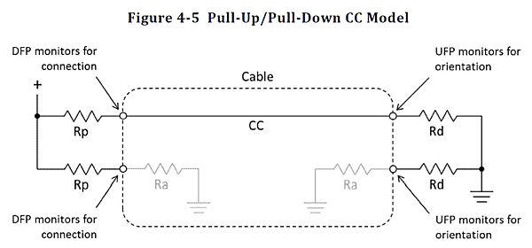
(1) The downstream facing port (DFP) is the host end and the upstream port (UFP) is the device end. The CC pin on the DFP has a pull-up resistor, Rp, and the UFP has a pull-down resistor, Rd. (Rp determines the host’s ability to power the device)
(2) If the DFP is not connected to the UFP, the DFP’s VBUS has no output. When the DFP is connected to the UFP and the CC pin is connected, the DFP CC pin detects the UFP pulldown Rd indicating it is connected to the device, the DFP turns on the VBUS-FET switch and sends VBUS power to the UFP, which is, before the CC pin configuration is detected, the VBUS does not power the UFP.
(3) It is clear from the figure above that apart from Ra, the rest of the resistance should not appear in the wire. The Ra value is a range value as described in the table below. Generally, 1K ohms is used, and if the cable is used as a power supply device it can be a little less than 800 ohms
(4) The value of Rp is regulated. The 56,000 ohms commonly used today is defined as standard USB power typically used to support traditional USB architecture. Hence the USB2 Type-A/B to Type-C cable. 0/USB3.0 is often added with this resistor at the Type-C end. Other resistance values are listed in the following table:
| DFP Advertisement | Current Source to 1.7 – 5.5 V | Resistor pull-up to 4.75 – 5.5 V | Resistor pull-up to 3.3 V ± 5% |
|---|---|---|---|
| Default USB Power | 80µA ± 20% | 56kΩ ± 20% (Note 1) | 36kΩ ± 20% |
| 1.5A @ 5V | 80µA ± 8% | 22kΩ ± 5% | 12kΩ ± 5% |
| 3.0A @ 5V | 330µA ± 8% | 10kΩ ± 5% | 4.7kΩ ± 5% |
(5) Rd is only 5.1K ohms in the specification and will not be used in Cable.
(6) Cable with Ra must have E-Mark IC inside, so they all support PD protocol. The cable without Ra must be passive and has no IC inside. Therefore, it must not support PD protocol.
(7) CC PIN detection can be divided into the following results:
| CC1 | CC2 | State | Position |
|---|---|---|---|
| Open | Open | Nothing attached | N/A |
| Rd | Open | Sink attached | ① |
| Open | Rd | Sink attached | ② |
| Open | Ra | Power cable without Sink attached | ① |
| Ra | Open | Power cable without Sink attached | ② |
| Rd | Ra | Power cable with Sink or Vconn-powered Accessory attached | ① |
| Ra | Rd | Power cable with Sink or Vconn-powered Accessory attached | ② |
| Rd | Rd | Debug Accessory Mode attached (Appendix B) | N/A |
| Ra | Ra | Audio Adapter Accessory Mode attached (Appendix A) | N/A |
| State | Source Behavior | Sink Behavior |
|---|---|---|
| Nothing attached | Sense CC pins for attachment, Do not apply VBUS or Vconn | Sense VBUS for attach |
| Sink attached | Sense CC for orientation, Sense CC for detach, Apply VBUS and Vconn | Sense CC pins for orientation, Sense loss of VBUS for detach |
| Power cable without Sink attached | Sense CC pins for attachment, Do not apply VBUS or Vconn | Sense VBUS for attach |
| Power cable with Sink or Vconn- Powered Accessory attached | Sense CC for orientation, Sense CC for detach, Apply VBUS and Vconn | If accessories are supported, see Source Behavior with the exception is that VBUS is not applied, otherwise, N/A. |
| Debug Accessory Mode attached | Sense CC pins for detachment, Reconfigure for debugging | Sense VBUS for detach, Reconfigure for debugging |
| Audio Adapter Accessory Mode attached | Sense CC pins for detach Reconfigure for analog audio | If accessories are supported, see Source Behavior, Otherwise, N/A |
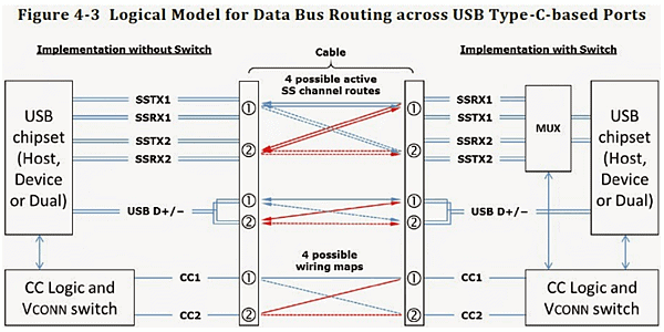
(8) Detection of Direct & Reverse connection: Because Type-C supports forward and reverse connections, the CC pin is used to detect forward and reverse connections when CC1 receives pulldown (Rd), from the DFP point of view it is a direct connection when CC2 pulldown receives a reverse link. After the forward and reverse link detection, the corresponding USB signal is output, for example, CC1 corresponds to SSTX1 and SSRX1. The right side of the figure below integrates MUX because the data rate of USB 3.1 is up to 10Gbps, to avoid the PCB alignment bifurcation, the signals coming from the link are changed back and forth from MUX, on the forwarding link to SSRX1 and Switch SSTX1, switch to SSRX2 and SSTX2 on the reverse link.