USB-C / TYPE-C Role Identification
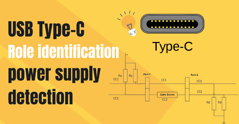
Functional identification of both sides of the TYPE-C interface is actually established by detecting the two DC lines on the TYPE-C interface. As shown in the image below.
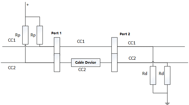
Here the cable device refers to the eMark chip cable to be used by the Vconn power supply when a CC switches to Vconn for the Emark power supply with the Emark chip cable to confirm the source side address of another CC can communicate with the device via direct current, this cable temperature feedback, support current information, for high charging safety or great help.
- Interface 1(Port 1): the power side and pull-up resistors (Rp) are added to the two DC lines of the interface.
- Interface 2(Port 2): as a current sink, a pull-down resistor (Rd) is added to the two DC lines of the interface
- If two interfaces are connected and interface 1 identifies the pair’s Rd drop-down menu, the connection is successful and the pair is identified as the power-consuming part.
- If port 2 identifies the pair’s pullup Rp, the connection is successful and the pair is identified as a power source. When two interfaces of power supply or consumers are connected, none of them can identify the desired one. Drag Rd down or Rp up, and neither can work.
For a dual role (DRP) interface, the two CCS constantly switch between the Rp upstate and the Rd downstate.
When connected to a non-dual capability device, the interface will stop in the provisional Rd state if the other side is using the provisional Rp mode. In this case, the power supply function of the interface is the power consumer:
When the other side is in the Rd pull-down, the interface will stop in the Rp pull-up state, and the interface power supply function is the power supply side. When connected to a dual-function device, both sides stop randomly in the Rp pull-up state or in the Rd pull-down state. The part that stops in the Rp pull-up state is the electricity supplier, and the part that stops in the Rd pull-down state is the electricity consumer.
Whether power supply or communication function, the output function determined upon connection is not always the same. You can change the function via the power supply protocol. The details will be described later. A product is designed as a pure electricity supplier and its communication function is UFP. Since the product’s power supply function can only be the electricity provider during the connection, the communication function during the connection is DFP. After connection, the product needs to switch the communication function to UFP via the power supply protocol.
USB-C / TYPE-C Power Supply Detection
The Type-C specification tells the power-consuming part the current capacity of the standard power supply according to the Rp resistance values of different power sources, while the Rd resistance values of the power-consuming part are usually fixed.
| Supply Current Capacity | Rp Value (current driver) | Rp value (5V driver) | Rp value (3.3V driver) |
|---|---|---|---|
| 900mA | 80uA±20% | 56kΩ±20% | 36kΩ±20% |
| 1.5A | 180uA±20% | 22kΩ±20% | 12kΩ±20% |
| 3.0A | 330uA±20% | 10kΩ±20% | 4.7kΩ±20% |
Rd of the power consumption side is defined as follows:
Rd = 5.1kΩ±20%
| Supply Current Capacity | Rd Voltage Value |
|---|---|
| 900mA | 0.15~0.61V |
| 1.5A | 0.70~1.16V |
| 3.0A | 1.31~2.04V |
The above is the fixed or standard power supply. In fact, according to the PD protocol, more power supply can be achieved by negotiating the CC pin signal.
Recommended Reading:
- STMicro Powers Industry Growth with 8 Inch SiC Push
- Green Web Transformation: Save and Earn Money
- How US Tariffs Will Impact Semiconductor Companies

Disclaimer: DiskMFR maintains a neutral stance on all original and reposted articles, and the views expressed therein. The articles shared are solely intended for reader learning and exchange. Copyright for articles, images, and other content remains with the original authors. If there is any infringement, please contact us for removal.


